
Interpreting MHD Datalogs - N54 N55 335i 135i 535i
| Boost Monkey
How to Datalog
1. Press the Monitor (auto log) button
2. Stabilize around 2500 rpm in 3rd gear with DTC fully off
3. Mash the pedal, shift at 6000 and hold at 2-3s after the shift into 4
4. Slow down, stop the monitor.
5. Then upload the .csv file in MHD / datalog to datazap.me (Autologging saves to SD card > MHD flasher > datalogging. Upload straight from MHD to datazap; it'll take you directly to the folder.)
*** PLEASE NOTE THAT DATALOGGING SHOULD BE DONE IN A SAFE AND CONTROLLED MANNER AND NOT ON PUBLIC ROADS. ALWAYS OBEY LOCAL TRAFFIC LAWS. ***
MHD Operation
A flash tune is targeting an engine load, aka a power level. Boost is just one component of power so depending on weather, and other conditions, the DME modulates the boost target to achieves its power level (engine load).
Wastegate Duty Cycle - The more open (higher %) the WG is the more boost the system is trying to build. The greater the % the more vacuum reaches the WG Actuators keeping them shut which builds more boost. o It’s important to note that with the N54 the vacuum keeps the actuators shut which is opposite of many other manufacturers where vacuum is used to open the wastegate(s)

Fuel Pressure Low Sensor (psi)
<50PSI sustained LPFP (Low Pressure Fuel Pump) is not acceptable - The occasional dip below 50PSI is not usually a cause for concern, it’s a sustained pressure below 50PSI that is typically indicative of a failing LPFP or perhaps a high ethanol content fuel coupled with an aggressive tune, in either case the LPFP should be addressed. - The LPFP feeds fuel to the HPFP and a failing/overworked LPFP can start to “pull down” the HPFP
Rail Pressure (psi)
<1400PSI sustained High Pressure Fuel Pump (HPFP) is not acceptable under high load
- Octane too low (may need to add ethanol or use a higher octane fuel)
- Spark Plugs and Ignition Coils are worn (on a tuned N5x it’s a good idea to replace plugs at max. 15k miles and coils every 60k miles)

- Short term fuel trim refers to adjustments being made in response to temporary conditions.
- Short term trims at idle should be in the +/- 3% range.
- Short term trims at WOT should not be pegged at -34 or +34. And within 10% from one another.
- Correlation between AFR and STFT’s: if you notice that the AFR is lower (aka less air aka richer) on Bank 1 or 2, chances are that the STFT for that bank will also be lower as the DME is reducing the amount of fuel that bank requires
- Subtractive corrections are better than corrections that add fuel
Long Term Fuel Trims (LTFT’s)
- Long term fuel trims are used to compensate for issues that seem to be present over a longer period.
- Long term fuel trims generally should not exceed +/- 10%
Boost Target (psi)
- Boost target is a function of load requested. Generally a 150 load is only around 12.5psi.
- When actual boost is off of boost target in the middle RPM range by more than 1 to 2 PSI it is indicative of a boost leak (check vacuum lines, IC couplers, CP, vacuum solenoids, boost solenoids etc.)
- Rule of thumb - at 2500/3000RPM, you need ~500rpm on stock turbo’s to reach your target minus 1-2 psi (i.e.14, if your target is 15), after that spool slows down to land a bit more softly on target

- This reading is pre-throttle body, boost spikes during shifts or on the release of throttle is normal. The system will build pressure during the short time the throttle closes and before the diverter vales open.
- This is the pressure, in PSI, in the charge pipe just before the throttle valve.
- Note this value does not necessarily represent the boost pressure in your intake manifold. If the throttle body closes more than around 70% it will progressively lower the boost pressure observed by the engine, but also progressively increase the boost pressure read by the TMAP sensor
Boost (psi)
- This is the calculated boost inside the manifold after the TB
- This reading will drop during shifts or on the release of throttle

^ As soon as the throttle is lifted (purple) the boost mean (yellow – before the TB) spikes and boost actual (orange – after the TB) drops
Lambda (aka air/fuel)
- A nice flat or slightly decreasing Lambda (for both Bank 1 and 2) is healthy
- Typical values are 14.7:1 at light engine loads decreasing to around 11.5 to 12 under heavy engine loads and high rpm.
- It's common to target 14:1 at peak torque and 12:1 at peak HP for example. It is also normal to have the AFR display 235:1 when car is coasting in gear or under a misfiring condition where the DME will cut off fuel to the misfiring cylinder(s).
- Both Bank 1 & Bank 2 should jump to 234.95 the moment you lift the pedal after being WOT. If Both Bank 1 and Bank 2 don’t shoot up at same time could be indicative of leaking injectors in the corresponding bank.
- MHD OTS tunes target Lambda of ~14.7:1 taper to 11.5:1 for pump tunes, and 12 – 12.5 for ethanol mix tunes.
-With a Stage 1 Tune a Lambda that starts off around ~14:1 and tapers to 11.8:1 as you approach redline seems about normal

Lambda shooting up to 234.95 immediately after throttle lift off
IAT (Intake Air Temperature)
- Measured by the TMAP sensor (Temperature Manifold Air Pressure) combination sensor
- Typical values for a car with the stock FMIC (Front Mount Inter Cooler), not running in boost, is 20°F degrees above ambient. With the onset of a boost condition, the temperature will rise quickly as boost rises and also with the length of time of the pull. Values quickly go from the normal 20°F degree rise above ambient to perhaps a 70°F to 90°F degree rise.
- The best upgraded FMIC will start out with only a 10°F degree rise when not under boost and will limit the temperature rise to only about 25°F degrees over a several gear pull.
- IAT over 140°F is too hot for the engine, and hinders power.

A high quality aftermarket FMIC, IAT delta between start and end of pull is only 15°F
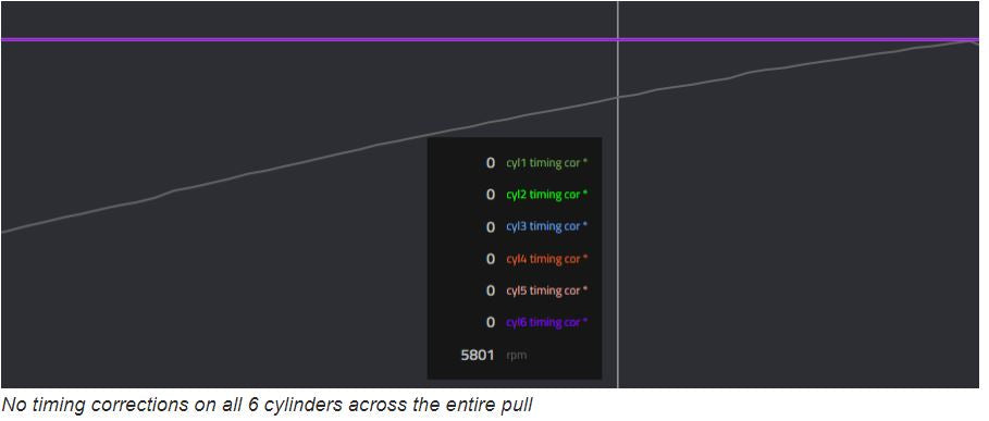
- Ignition Advance is the number of crank degrees BTDC (Before Top Dead Center) when the spark is turned on to ignite the fuel/air mixture in the cylinder. Generally higher engine loads/boost levels require less advance because the burning process progresses faster (less time to complete) under higher cylinder pressures. Higher engine rpm (under constant load) generally requires more ignition advance because there is less time for the cylinder pressure to build up before the piston starts it’s downward stroke.
- The DME can adjust timing on a cylinder by cylinder basis using an advanced knock sensor system with long term (octane detection) and short term (knock detection) trims analogous to a fuel trims. - The displayed values can change a large amount under light to moderate loads more than 30 degrees on some engines. - WOT (Wide Open Throttle) will result in a much narrower range of values usually dish shaped with values in the 5 to 13 degree range over the ends of the rpm band and a minimum valley value of about degrees lower.
- Of more importance is watching out for sharp drops of more than 3 degrees in the engine high torque/power band.... typically in the > 4500 rpm range. Repeated / concurrent corrections on several cylinders in gear point to an overly aggressive tune for the car mods and fuel.
- Also note the DME will raise and lower advance as a function of normal mapping like during traction control events, gear changes, etc, and such drops are completely normal.

No sharp drops in timing
- Many throttle closures could be indicative of traction/stability control not being fully switched off during the pull
- Throttle closures are not ideal and should be minimum or preferably nonexistent, however throttle closures are part of the DME’s control strategy
- -Throttle closures were common on V5 and to some extent on V6 maps, this has been addressed for V7 maps

Leave a comment
Your email address will not be published.